

Projects:
GTO
My
67 Pontiac GTO
Trunk Body Work
-Trunk pans
-Wheel wells
Body Work Part 1
-Rear Quarters
-Rear Door Jambs
-Window Reveals
Body Work Part 2
-Cowl
-Pillar
-Rocker
Body Work Part 3
-Windshield channel
-Doors
-Fenders
GTO Paint
-Filler work
-Priming
-Blocking
GTO Frame Work
GTO Convertible Top Pt 1
-Top Frame
GTO Convertible Top Pt 2
-Top Trim
GTO Drivetrain
-Engine
-Quadrajet Rebuild
-Exhaust
-Axle
Muncie
Rebuild
popular
Auto to Manual Swap
1967
Ram Air GTO
story
Wheelhouse Filler template PDF
Willys CJ3A
CJ3A Intro
Engine and REBUILD
Drivetrain
BodyWork 1
BodyWork 2
BodyWork 3
BodyWork 4
Paintwork 1
Paintwork 2
Final Assembly
Final Assembly 2
Electrical System
Other Rods
TJ Wrangler Rubicon
CJ7
CJ8
Decrepid Dakota
Powerdyne Minibike
Allis Chalmers B engine rebuild Part 1
Allis Chalmers B engine rebuild Part 2
Allis Chalmers Generator to Alternator conversion
Gizmos
Stereo camera
rig
Stereo mic preamp
About:

Feeds

Markup
Allis Chalmers B Engine Rebuild Part 2
click here for Part 1
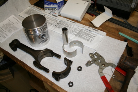
Piston and Rod Assembly
The piston and rods were now ready to be assembled and installed into the engine block. Here are the parts ready to be assembled. The pistons are new and come with the kit. The rods are to be re-used. the small end features a bolt that pinches the small end of the rod onto the wrist pin.
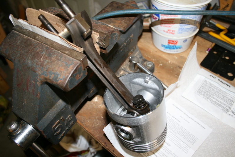
The rod, wrist pin and piston are fit together and then the rod's small end bolt is torqued to 35 ft lbs. The connecting rod large end bolts are offset from the center. #1 and #3 rod bolt locations are biased toward the front of the engine, and #2 and #4 are biased toward the back. Pay attention with the aftermarket piston as it appears the rod will work whether it is installed correctly or backwards. So, in other words, the wrist pin bolt on piston #1 and #3 face the cam, #2 and #4 face away from the cam.
The piston rings and bearing shells were installed.
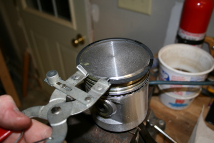
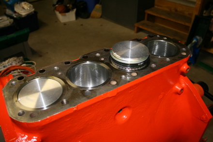
The pistons were installed into the cylinders. A ring compresser (not shown) made easy work of it.
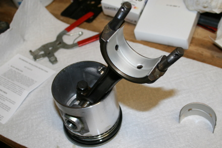
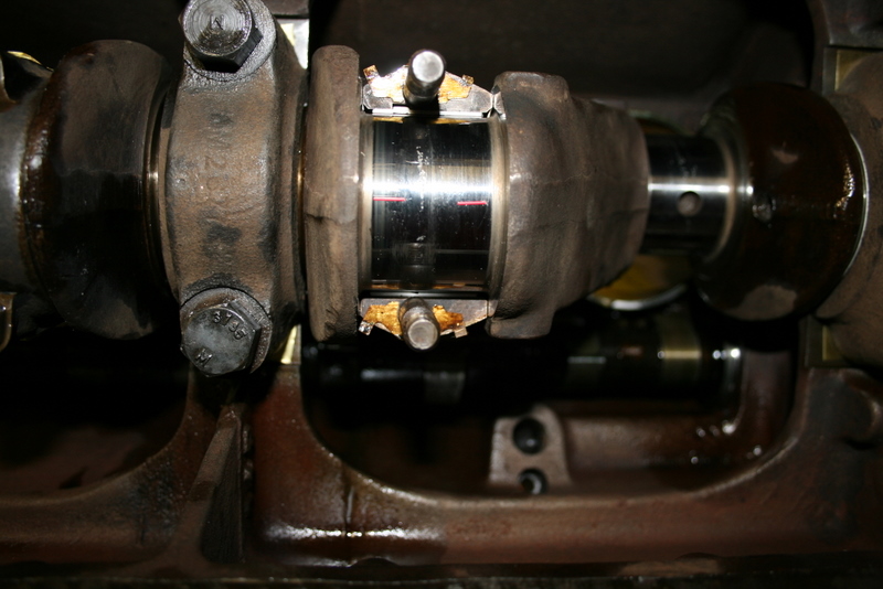
Here you can see a piston rod slipped onto the crankshaft. You can see the offset of the rod bolts mentioned above; the bolts either are closer to the front side of the engine or to the rear. Also you can see I've put in the original 0.010" shim stack and I've got plastigage ready for installation of the rod cap. I'll torque the cap and see what the bearing clearance is to start with.
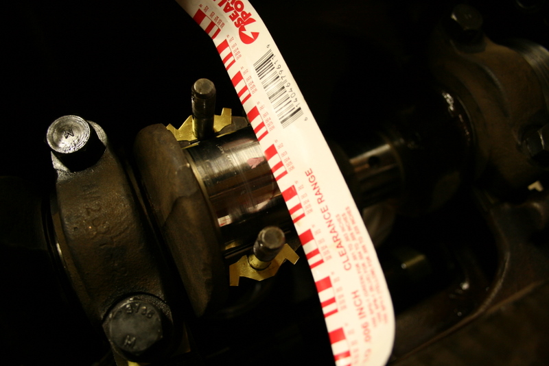
So I'm doing the same procedure for the piston rods as I did with the crank mains. Start out with a 0.010" stack, measure what I've got for clearance with plastigage, then reduce shim stack thickness to get bearing clearances to spec. Same deal here, all clearances were too big with the original 0.010", so all shim stacks had to be reduced to either 0.007" or 0.008" to get the close to the 0.002" specification clearance between the bearings and rod journals.
Here's the readout from the plastigage. It was tricky working with the plastigage as it would get mangled upon removal of the rod cap. Note also the home made brass shims.
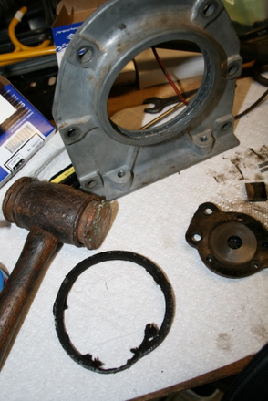
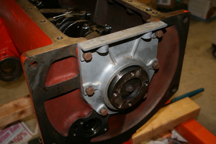
Rear Main Seal
The rear plate houses the rear main seal. The original was felt. I ripped it out and installed the supplied cork replacement. The crank has a spiral groove that moves the oil back into the crank case as the crank rotates.
I glued in the cork seal into the rear seal housing with red RTV, let it sit overnight, then muscled the assembly onto the engine (It's hard to push that new cork seal over the oiled crank). I used RTV between the seal housing, gasket and block. The manual says I should have copper washers for the bolts, but they were plain old lock washers. I reused them. Here's the rear main seal plate installed onto the block.
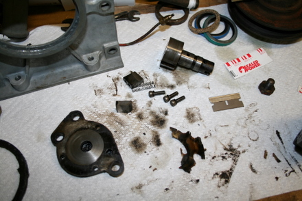
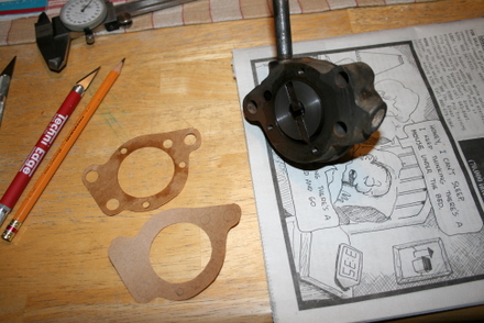
Oil Pump
The oil pump is bolted onto the back of the engine and meshes right onto the back of the cam. It was taken apart and inspected. There are springs that separate two "blades" which whirl around an eccentric bore. The springs help keep the blades against the outside of the bore. I need new springs as one is shorter than spec.
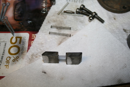
Here are the new springs between the oil pump blades. The manual says they should have about a half a pound pressure at 0.750" compressed length. I could not find exact sized replacement springs so I used what was closest in size. The spring manufacturer has a formula to calculate what the spring pressure will be at a given compression. These fit the bill, a 0.120" diameter, 0.014 wire diameter, 1 inch length.
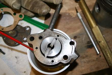
The oil pump was re-assembled. The cover must be of a certain gap to the pump body. This is accomplished with the gaskets. I ended up having to make a few gaskets with paper bag as gasket material to achieve the correct gap.
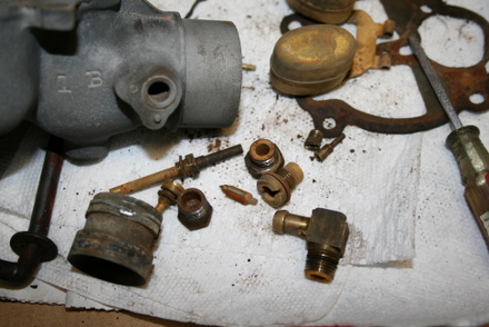
Carburetor
The carburetor is a Zenith model which is very common for these old tractors. It's cast iron and uses a bunch of brass parts internally. There was a bit of corrosion and I had to use torch heat to remove some of the brass parts. I can't believe the thing ran,
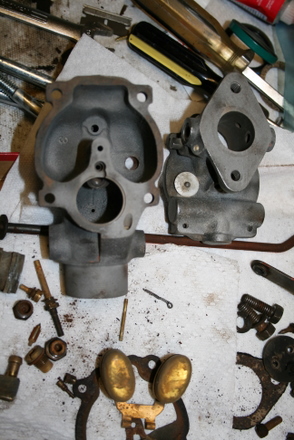
The main castings were sand blasted to clean them up.
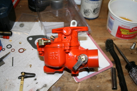
The carb was rebuilt and painted.
Crank Snout Seal
This section pertains to the front crank snout seal. The AC B engine uses cork seals throughout, and the front crank snout is no different. The crank snout has a spiral groove cut into the seal surface that swipes oil back into the crank case as the crank turns. Apparently these seals are not easily obtained and the kit we bought did not have the correct thick cork seal.
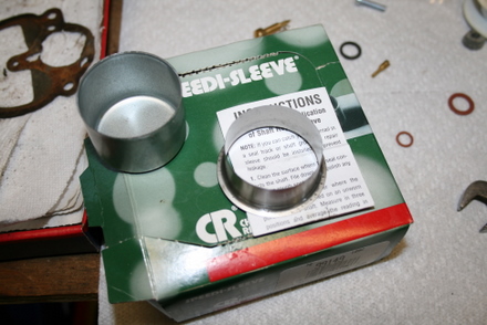
Lots of folks have suggested that the wide spiral cut can be covered with a "speedi-sleeve" kit. Speedi sleeves are thin stainless sleeves that are bonded over worn or damaged shafts and create a new sealing surface. Then conventional rubber lip seals can be used. I purchased the 50 dollar kit and a correctly sized rubber lip seal to go with it.
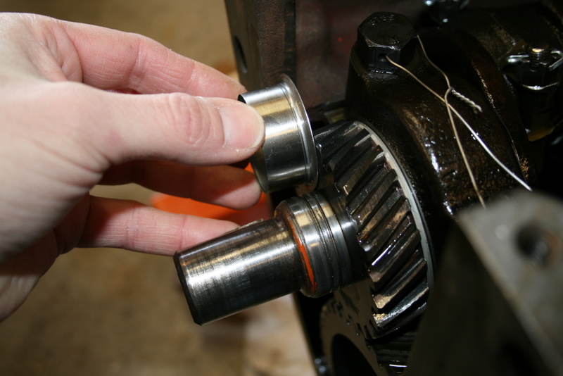
The installation "cup" is meant to push the sleeve onto the shaft by pressing on the lip at the bottom of the sleeve. The cup ended up being useless as the crank snout was long and the cup wasn't deep enough.
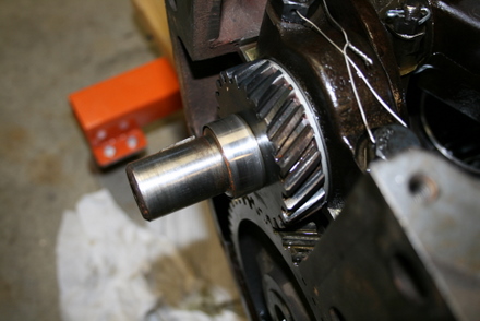
With a range of plates and pieces of pipe, I managed to get the sleeve pressed on.
A conventional lip seal was pressed into the timing cover plate.
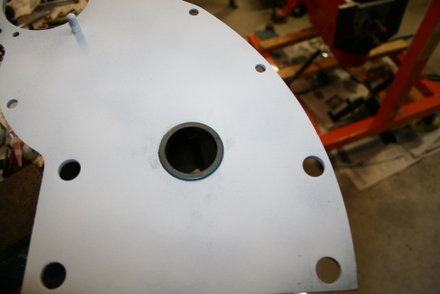
It was apparent however when fitting the plate onto the front of the engine that the lip seal housing ID was extremely close to the OD of the sleeve. And indeed it only lasted for a few days, for the rubber lip wore through and oil started to pour through the front seal. The speedi sleeve "fix" idea was a failure.
Not wanting to employ any "sleeve" technique, I took another look at the original seal. It was basically a flanged ring, with a cork seal inside, and a large washer staked on top to retain the cork. I decided to "rebuild" this seal.
I carefully bent back the stakes and removed the washer, then removed the remnants of the cork. I would have to fashion a ring of cork to put back into the seal. I could not find a supply of gasket grade cork 3/16" thick, so I decided to build up my own with 1/16" cork. I used rubber cement and made up a 3/16" gasket, then cut out the OD. Here it is before I cut the ID:

The seal was bonded into the flanged seal housing, then the washer was staked on, and I cut the ID out with a razor. The seal has worked perfectly since. Now, on to.....
More Assembly
The engine is starting to come together. Here you can see the oil pump has been bolted on. The oil filter housing is installed, but you can't see the new 1/4 inch riser tube inside the oil filter. This is what should be there rather than a wood dowel!

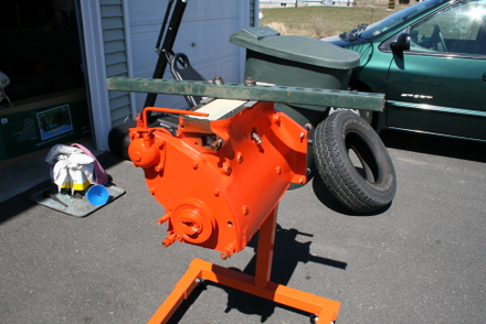
The engine was now ready to be taken to the farm and bolted back to the tractor. Here it is with some unistrut as a big handle to move it around.
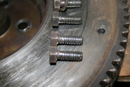
The flywheel and clutch were reinstalled. Some of the clutch cover bolts would not torque to 35 ft lbs while tightening. I thought the flywheel threads may be stripped, but upon taking it apart, I noticed that some of the bolts were stretched. Look at the second one up from the bottom. I've never seen bolts stretch this far and not snap. These are really crappy soft bolts. There are no markings on the heads, but then I see no markings on almost all of the tractor's bolts. I replaced with some grade 8 bolts.
The engine was installed onto the torque tube.
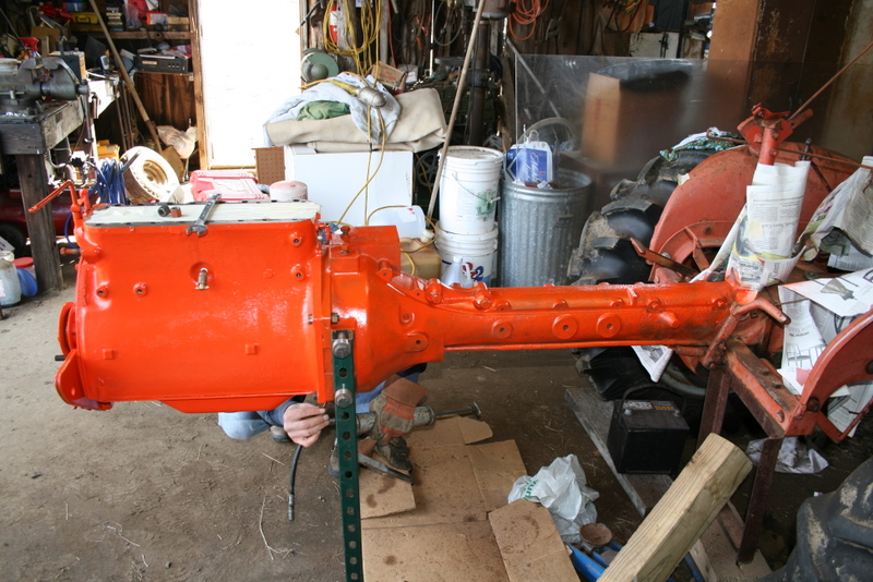
The front end was reinstalled, as well as the head and water pump.
Intake/Exhaust Manifold
The original manifold was spent, so we purchased a new one. The new manifold was pretty nice, and much meatier than the old one, but the port diameters were pretty small on the carb side and intake openings. I decided to get out my grinder and "gasket match" the openings. Here's a comparison of the old and new:

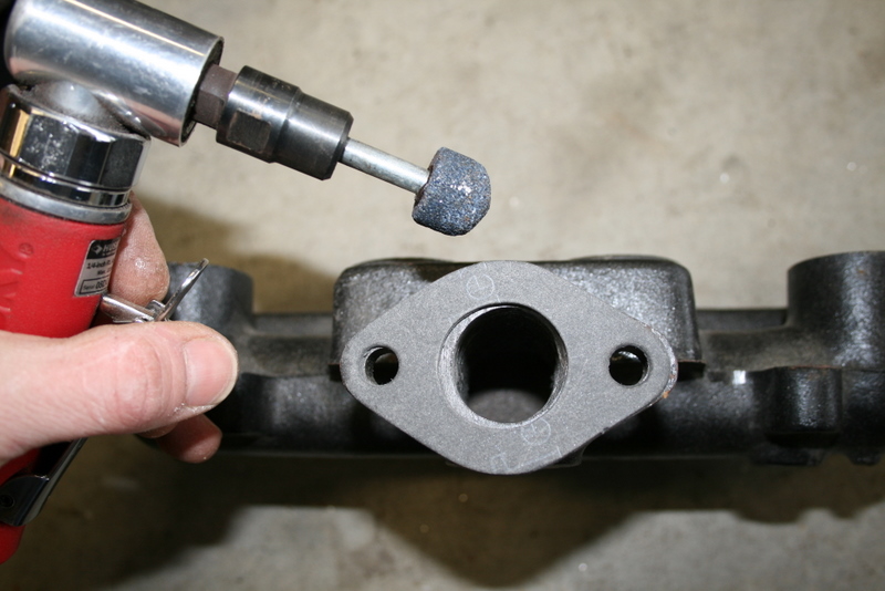
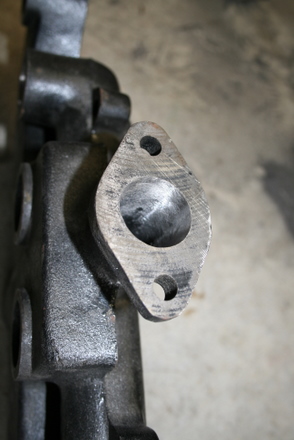
Here's the port after grinding. The grinding goes surpisingly fast.
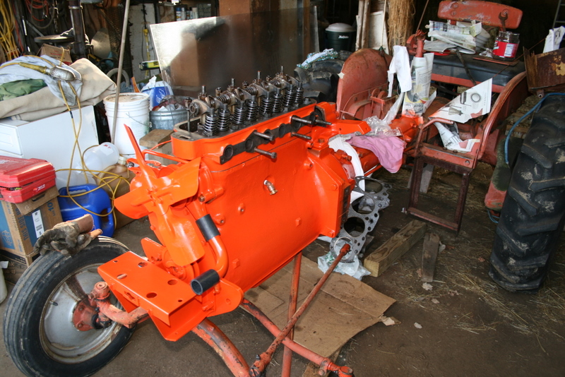
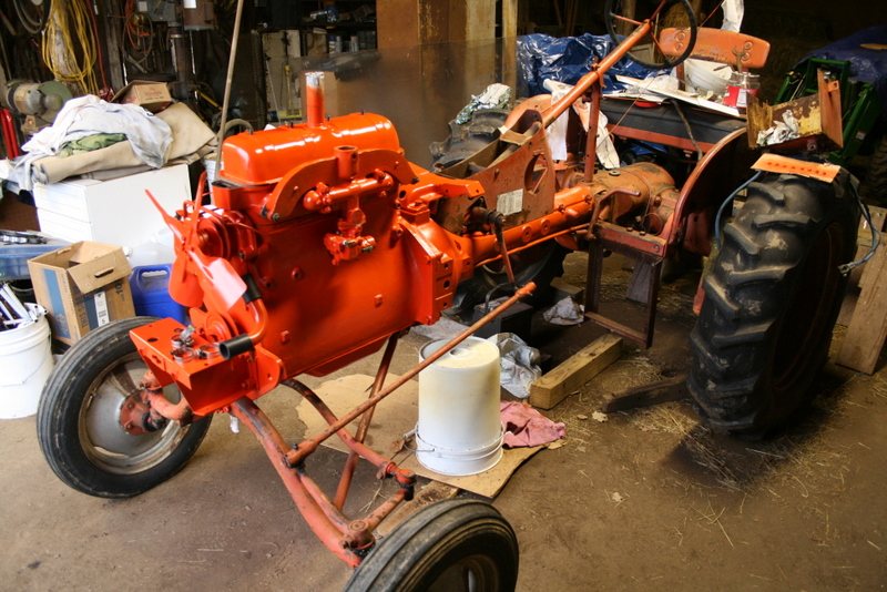
And here it is starting to look tractor-like again.
We were getting pretty tired of the job by this time so we abandoned all thoughts of sanding and prepping the cowl and gas tank. We just put it all back together. To see how the electrics were done, go to the Alternator conversion on Allis Chalmer B page
The engine was started with little fanfare and it ran like a champ. We had a few issues with rusty sediment in the gas tank, then the large gas tank at the farm was found to be 1/4 water, so we had to separate all the water out. But after that, it ran great! No oil smoke, no leaks, and it charges it's own battery! I've got a video of the thing starting, perhaps I'll post it soon...
To see part 1 of this rebuild, GO HERE
To see the Alternator conversion, GO HERE
SFS
Links:
Willys Jeep CJ3A Forum
There exists a nice set of webpages for CJ3A's. It's got a forum too that caters to both '3A's and CJ3B's. It's a great resource, and frequented by very knowledgible folks.
1967 GTO Original Owner
These two videos feature an original owner GTO. This car was featured in Hemmings Muscle Cars magazine a couple years ago. Part 2 has inside and outside shots of the owner driving the car. Very nicely done.
Blues Maker
"Mississippi" Fred McDowell. One of the great Bluesman. This is a documentary made in 1969.
Pinstripes
Pinstriping the ol' fashioned way. Pretty nice.
MGB Racecar
I've always liked MG's. Watch this MGB lift it's inside tire a few inches off the tarmac when going "'round the bend". Awesome.
Pepsi Throwback

Pepsi has put out a "limited edition Throwback" version of Pepsi with REAL sugar, instead of high fructose corn syrup which has been used since the 80's. Holy cow there IS a difference; it's WAY better. Find some quick!