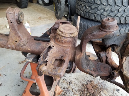
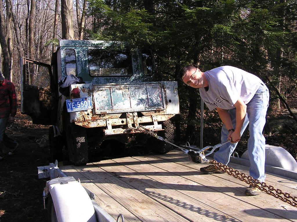
Remember when the Jeep Rubicon was introduced? Waaay back in late 2002? Ah
yes, the TJ Jeeps were hot. And Jeep had the audacity to put out a knockout
offroad package, the Rubicon. Dana 44 front axle, air lockers front and
back, 4 to 1 transfer case, 4 wheel disc brakes, WOW.
Well, I bought one in January of 2003. I still have it. It's served very
well and now has 163K miles. But it's been worn down a bit. Rust.
Not terrible (compared to some of the insanely rusted frame TJ's I've seen
repaired on youtube), but still enough to require attention.
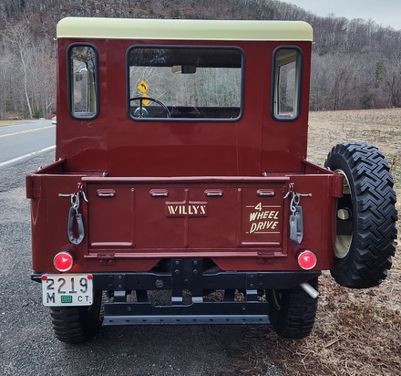
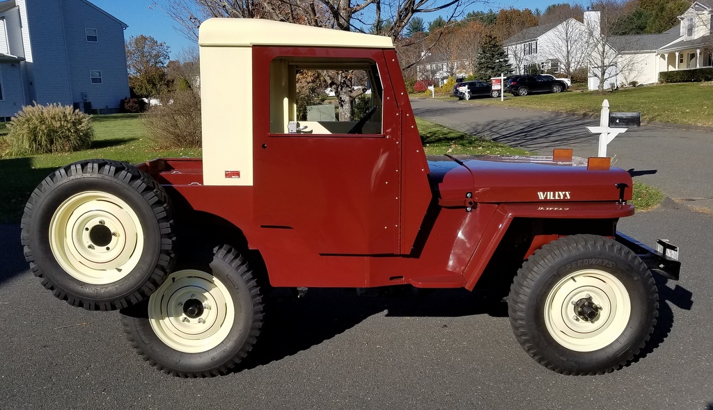
Here's a little update from the Jeep appearances department. Way back in the beginning of the hard top refurb, I thought I'd paint the whole top the ivory color. I did so, and I got some feedback from the home front that the color combo might be a bit ugly. Even for a Jeep. So, while my painting equipment was still out, I re-painted the doors and jambs red. It was better and I stopped there. Here's what it looked like:
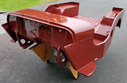
After some pondering, l thought maybe the rear and corner panels would look good red too, but I just didn't get around to it until this past fall (2022)...I wanted to get it done before it got too cold. I unscrewed the rear panels, cribbed the top panel up, and slipped the corner and rear top panels off the Jeep. There was window removal, scuffing, masking, mixing, spraying, and a smidge of buffing: Hey presto it's mostly red now (top photo). For a little more detail, go to the Flatfender Assembly page 2 and scroll to the bottom.
CJ3A Assembly Part 2, Final Report
March 2022
Part 2 of the final assembly of the CJ3A is here. Sorting out all the details in a comprehensive rebuild takes alot of time. But in the end you end up with a very reliable and fun to drive machine. Click here to check it out!
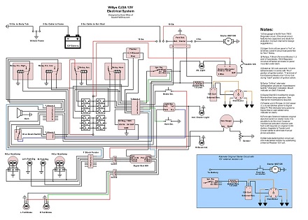
CJ3A Electrical System
February 2021
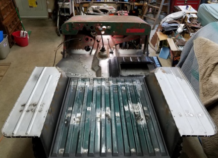
Back in 2017 when I put the CJ together for state inspection, I built a completely new electrical system from scratch. I gathered reliable, high quality materials, drew up a schematic and put it together. The intent was to get the Jeep rolling with minimal cost so practicality was king. The page covers a conversion to 12 volts, integration of a fuse panel with relays, a modern starter, turn signals, and more. Click here! to check it out.
CJ3A Update
February 2020
Update on CJ3A build. It's kinda done. Well they're never really done, but it's to a point where I can take it out anytime worry free and have a blast. I've been driving it all winter. So here's CJ3A Fnal Assembly Part 1.
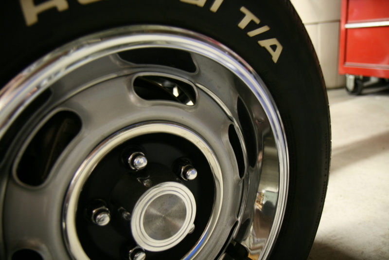
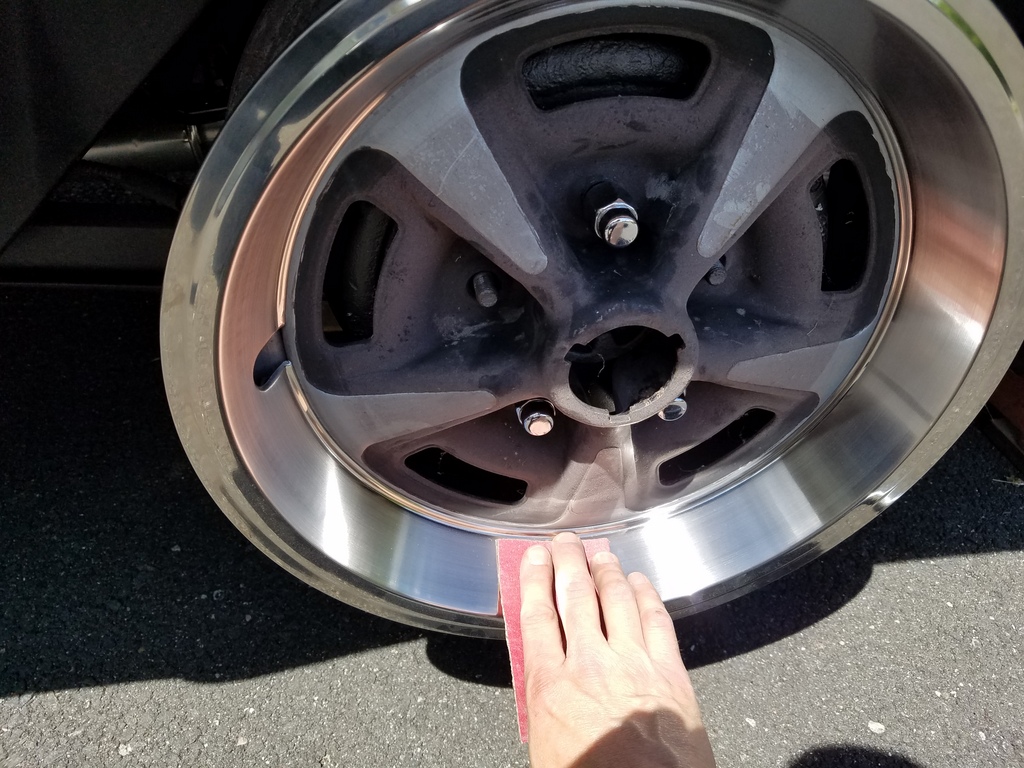
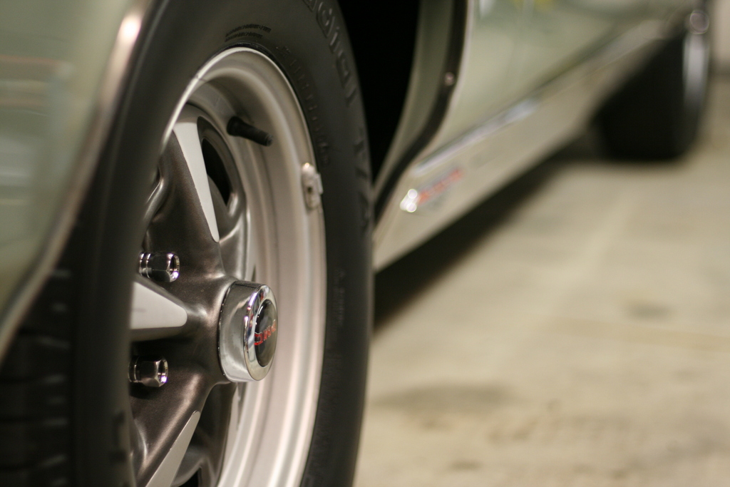
December 2019: GTO Trim Ring Report
Back when I first bought my GTO in the 80's, it came with steelies and hubcaps. I wanted to get rid of those as quick as possible so I went out seeking Rally wheels. Since Rally I wheels seemed to be nonexistent in New England back then, I bought some Rally II wheels. I ran those in the early years with a mash-up of mystery trim rings. The picture above is in 1988 with this setup.
After a stretch of time I managed to get a set of Rally I wheels. The Rally I's needed trim rings too, but it wasn't so easy: Rally I wheels need a narrow trim ring that nobody made back then (and even now the re-pops are wider than originals me-thinks?). To solve that problem, I bought a set of quality trim rings from JC Whitney (they offered nice quality ones up until the early 2000's but not anymore) and cut 6 reliefs in each one to clear the 6 slots of the Rally I wheel. The reliefs allowed a tight fit and looked good. These were not "brushed" like originals should be, but they were a great solution. Here are the slot reliefs I cut...basically trim off the underside lip where the slots are:
After the restoration, I thought I'd like to get back to running Rally II wheels with correct "brushed" trim rings. I managed to collect two used original style rings, but they are in tough shape.
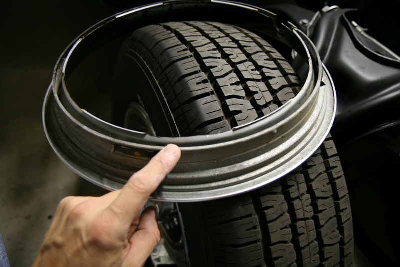
Ames offers new sets of brushed trim rings, but being the cheap yankee that I am, I suspected that there was nothing special about the process their supplier uses to "brush" them that I couldn't do myself. So I purchased the more common fully polished type trim rings from AMES; part number T111H. Here's a comparison of a T111H (on right) to what I believe to be an original brushed Rally wheel trim ring (on left):
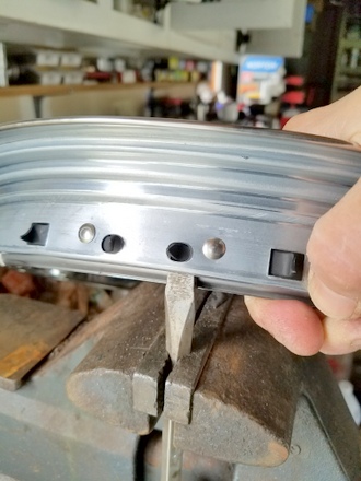
The new rings have a different style of retention using spring steel "tangs" that dig into the dish of the wheel rather than edge clips. The spring steel is thick and they don't "give" very well. In fact, in my first attempt at installing a ring onto a wheel, the tangs deformed their mounts and warped the whole ring. I can't see how they'd work as is. Close inspection showed that the tangs appeared to be sticking too far out exceeding their ability to conform to the wheel. Bending the tangs back a little bit seemed like a good solution. I mounted a heavy duty flat tip screwdriver in my vise and maneuverd the ring so that the tip
of the screwdriver contacted the base of the tang.
Light taps from a hammer bent the tangs to a more shallow angle. I only bent the tangs closest to the rivets. The following pictures illustrate the angle of the tangs...first picture is before modification:
Next picture is after modification (tangs bent down a bit):
They fit the wheels nicely, and I ran them in their fully polished state for the rest of that season:
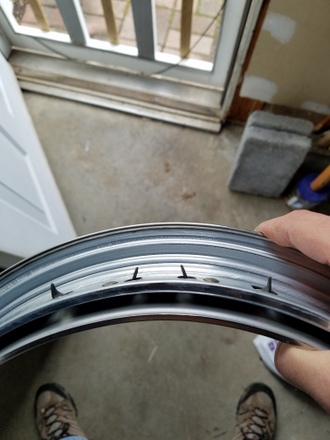
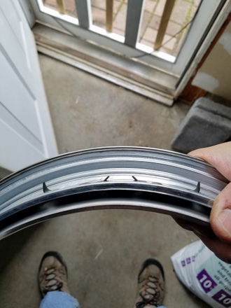
But I finally got up the nerve to make an attempt to "brush" them. I mounted the rings to a spare wheel, and mounted the wheel to my rear axle. I put the car into gear and sanded the wide face of the trim ring with 150 grit sandpaper, followed by a scotch-brite pad polish. I stayed away from the narrow face of the trim ring as this is supposed to remain shiny (as original). I'm happy with the result. DIY brushed trim rings:
This is the result (I like them):
CJ3A Paint Work Part 2 COLOR
November 2018
There is COLOR on the Jeep. I told you I'd do it. So I sprayed the tub with a pretty color very close to the original Luzon Red. It's been a ton of work due to some extensive paint repairs. Let's just say I don't like low VOC single stage. But the Jeep is coming together and I am very happy with how it's coming along. Check out CJ3A Paint Work Part 2.
CJ3A Paint Work Part 1
October 2018
In year 4 of the ressurection of this crusty old CJ3A, I finally sprayed some finish coatings in preparation for paint. Check out the CJ3A Paintwork Part 1 to see the filler work and prep all the way to spraying the 2K primer.
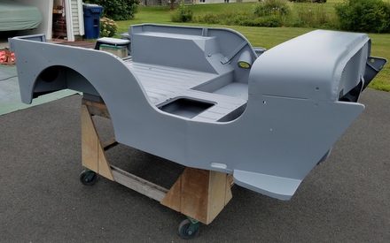
CJ3A Bodywork Part 4
August 2018
It's hard to fathom that a big chunk of a year has passed since my last entry. Yeah. The Jeep is not running yet, but it is painted. But I'm not ready to show that yet. I have to make a few interim entries first! Like CJ3A Bodywork Part 4. As we left off last February, I whipped the Jeep together in order to present a full working vehicle at an inspection station so I could get this thing legal in my name. I was successful. I was happy. And I then tore the Jeep apart. It's been a long slog to finish up alot of details, so check out the final entry for the body fabrication and paint preparation.
And I promise the shiny pictures will follow along soon.
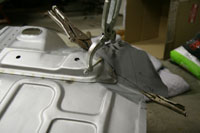
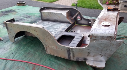
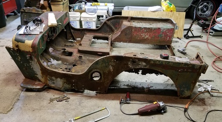
Work continues on with the ol' Willys CJ3A Jeep project. As noted in previous entries, the chassis and drivetrain are operational, but the body tub was severely rusted out. Replacement body tubs are available, but they are a bit pricey, and have their own issues. I wanted to rebuild the entire tub while keeping it as stock as possible. In this update, all rot has been removed and all flooring and bracing has been replaced. Click Here to check out Part 1 of the CJ3A Willys Jeep bodywork page.
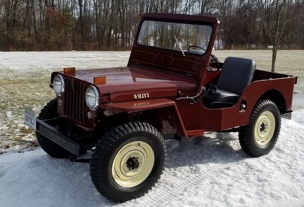
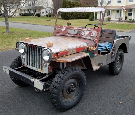
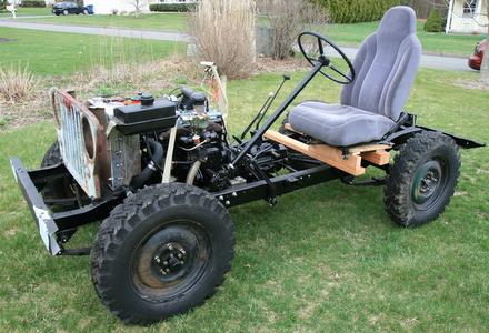
It Runs
January 22, 2017
After owning this little Jeep for ten years it's finally running. It stops too. To
read details about the final round of chassis work, click on the
picture and go to the Jeep CJ3A
Chassis and Drivetrain page. There's a link there too for a short
video of me tooling around the neighborhood.
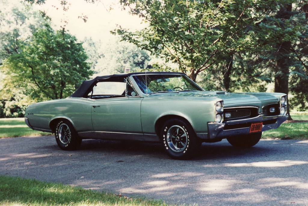
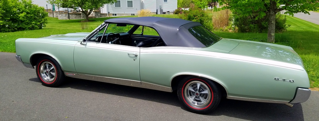
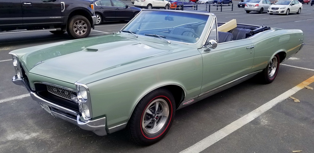
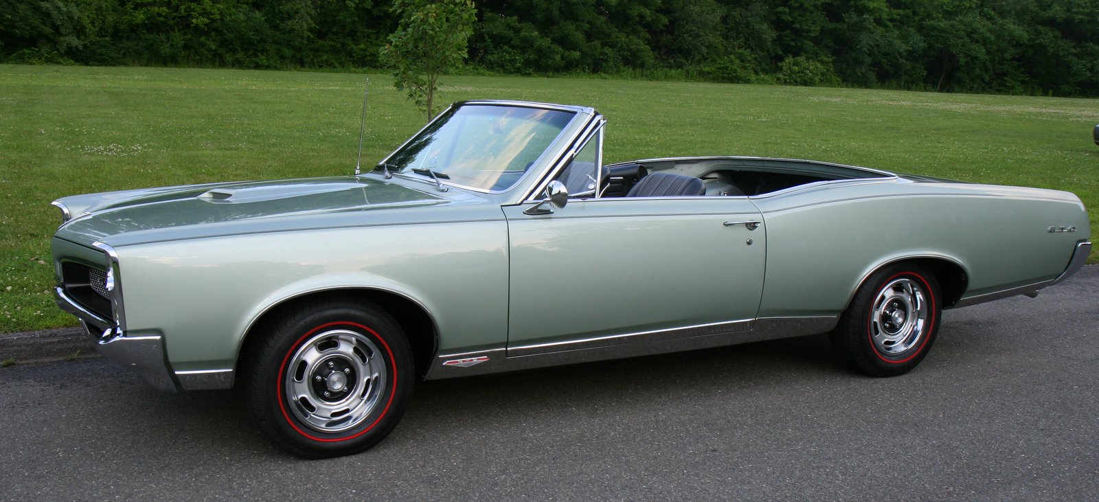
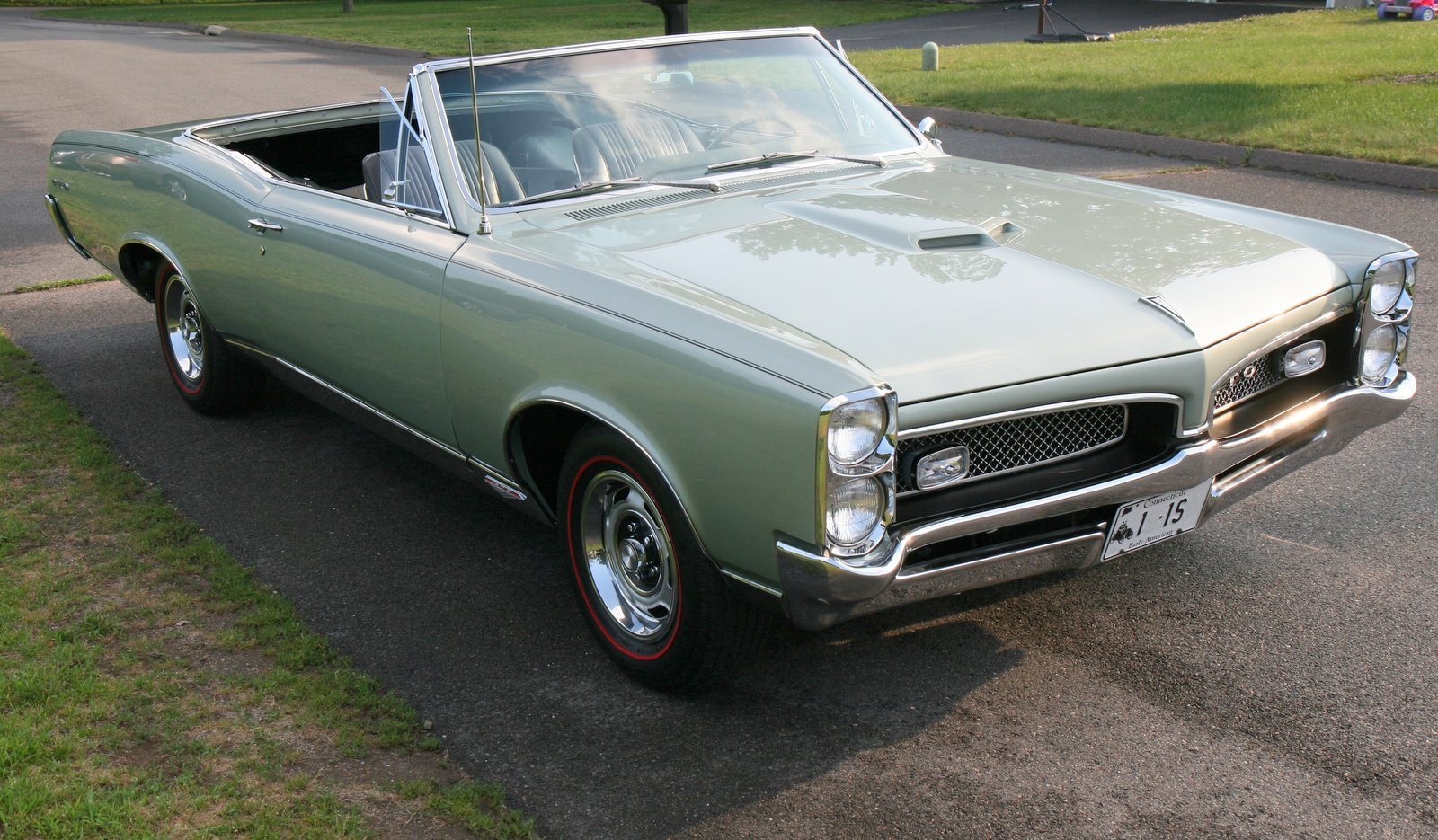
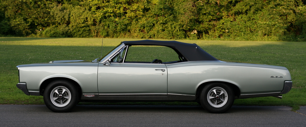
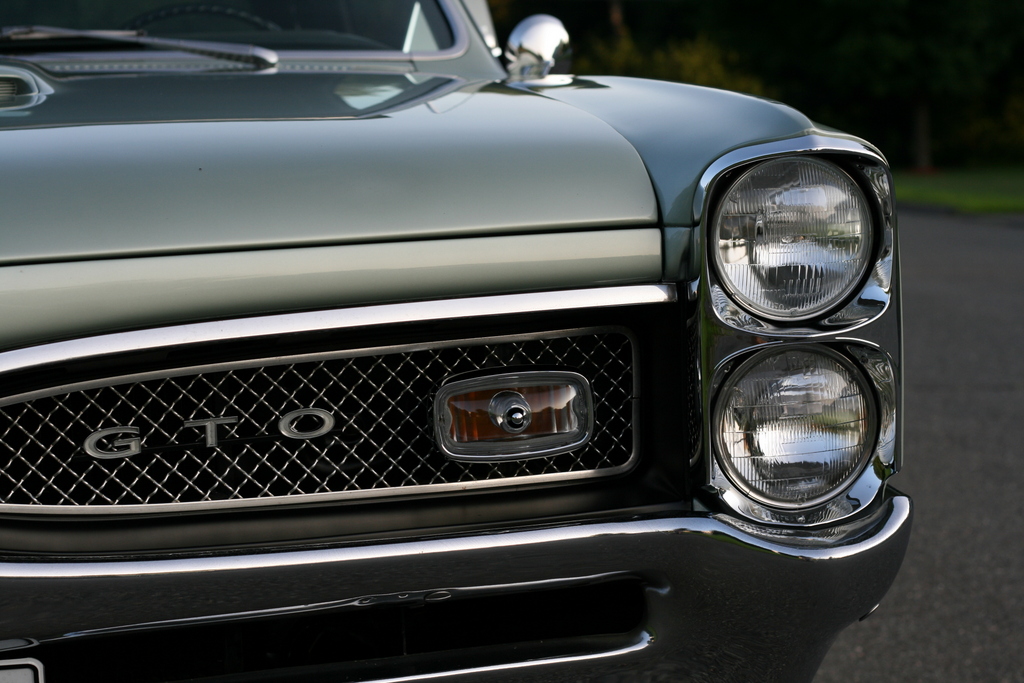
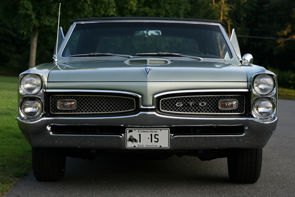
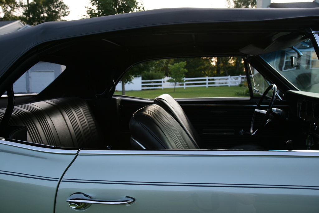
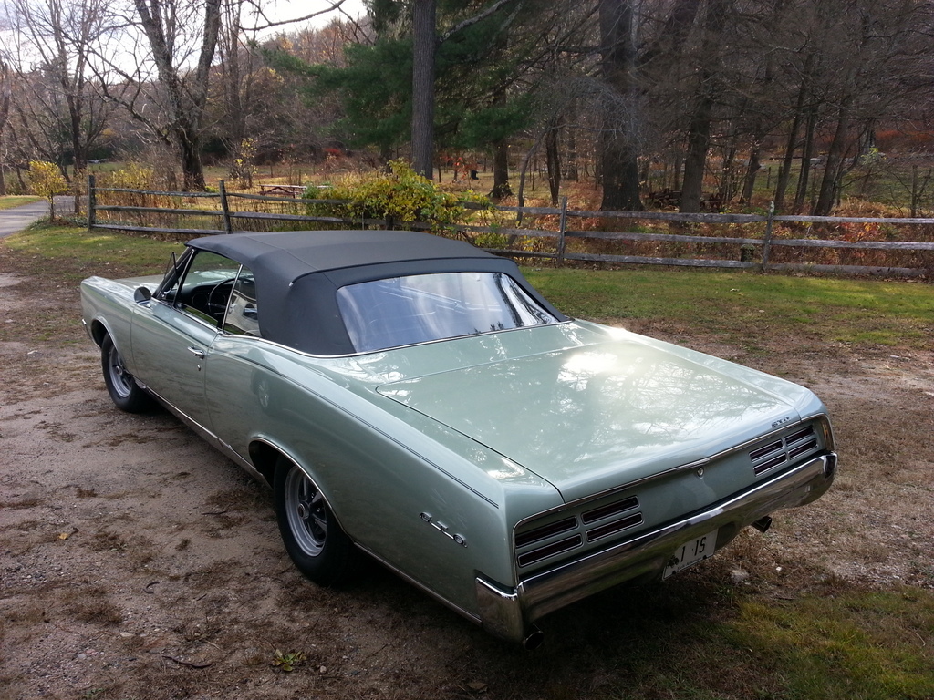
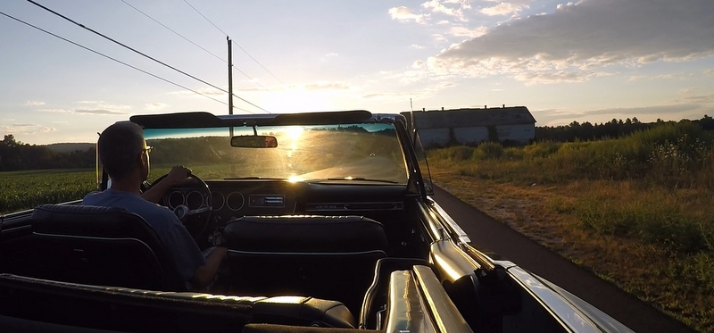
1967 GTO Current Status Report
February 2016
If you've
followed the GTO restoration process on these pages, you'll note that I
haven't updated in a long while, and indeed I've never
put up pictures of the "finished" GTO. This entry aims
to rectify that situation.
To recap:
In 2013, I finished
enough on the car to get it to a fairly
presentable state. I intended to post a bunch of pictures, but I kept
putting it off for several reasons:
1) I wanted to get the chrome work done,
2) I
never finished the interior,
3) I was never happy with any pictures I took.
Another reason could possibly be I
have a problem finishing stuff.
So, despite misgivings, I'm posting some
shots of the car... warts and all.
Shown
above is the car in early 2013 when it was mostly assembled,
but
before the new top. This was a full year after I had
painted the car. (Yes, it takes a long time to assemble a car in full
detailing mode.)
The redline tires were an awesome surprise
from my wife. She had them mounted on the Rally I wheels I had.
The car looked a little funny with no top frame installed:
I got the car running in the spring of 2013 but work
continued on projects such as the complete "re"-rebuild of the Muncie
transmission and the Quadrajet
upgrade.
In
the fall of 2013, I did the convertible
top installation. By the time I
got it done, the driving season for 2013
was pretty much at an end.
In 2014 I continued to just work on my punch list which
included getting the original AM radio up and working.
I also refurbished a set of JA code Rally II wheels
and mounted 15 year old BFG's on them. The car rolls
so
smooooooth with these
wheels. I hope to get a correct style trim rings for them this
spring.
Here's the car as it is now:
Note the indents on the front bumper from past bumper jack
action. I pounded out a few big dents on the rear bumper too.
I've just been enjoying the
car. It starts, runs and drives fantastic.
The big ticket items I'd still like to complete is a new
instrument cluster, seat upholstery and new chrome for the bumpers.
But, in a way, I don't mind the patina on the engine and bumper chrome.
When the budget gets better, those will be good future projects.
I hope to have a gopro video soon. I'll post it asap!
SFS
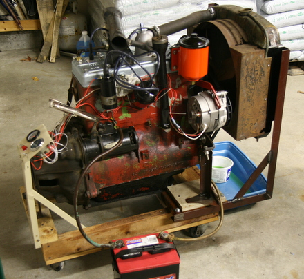
Willys L134 Flathead Test Stand
February 6th, 2015
I've
had the "Jeep bug" for a long time and my internal automotive radar has
a high
sensitivity for Jeeps. If you've scanned the links to the
left you might have noticed the story of my acquisition of a wee little
1950 Willys CJ3A in 2006. It was about to be scrapped after having
spent two or three decades (or more) out of commission
sitting out in the elements.
Despite it's advanced state of deterioration, I still felt
compelled to take it home. To see the details of what I dragged home
that day, see the CJ3A
introduction
page.
After
getting it home, a quick survey revealed it needed a replacement engine
and in 2009 I found one, but I stuffed it into a corner and the Jeep
continued to languish.
But recently, the Jeep
whisperings have been getting louder...and a window
of time has opened up at Squids Fab Shop.
It was time to get busy on
the Jeep. I decided the first thing I wanted to do was to hear the
new-to-me engine run. The engine was pulled out from it's dusty corner
to begin work.
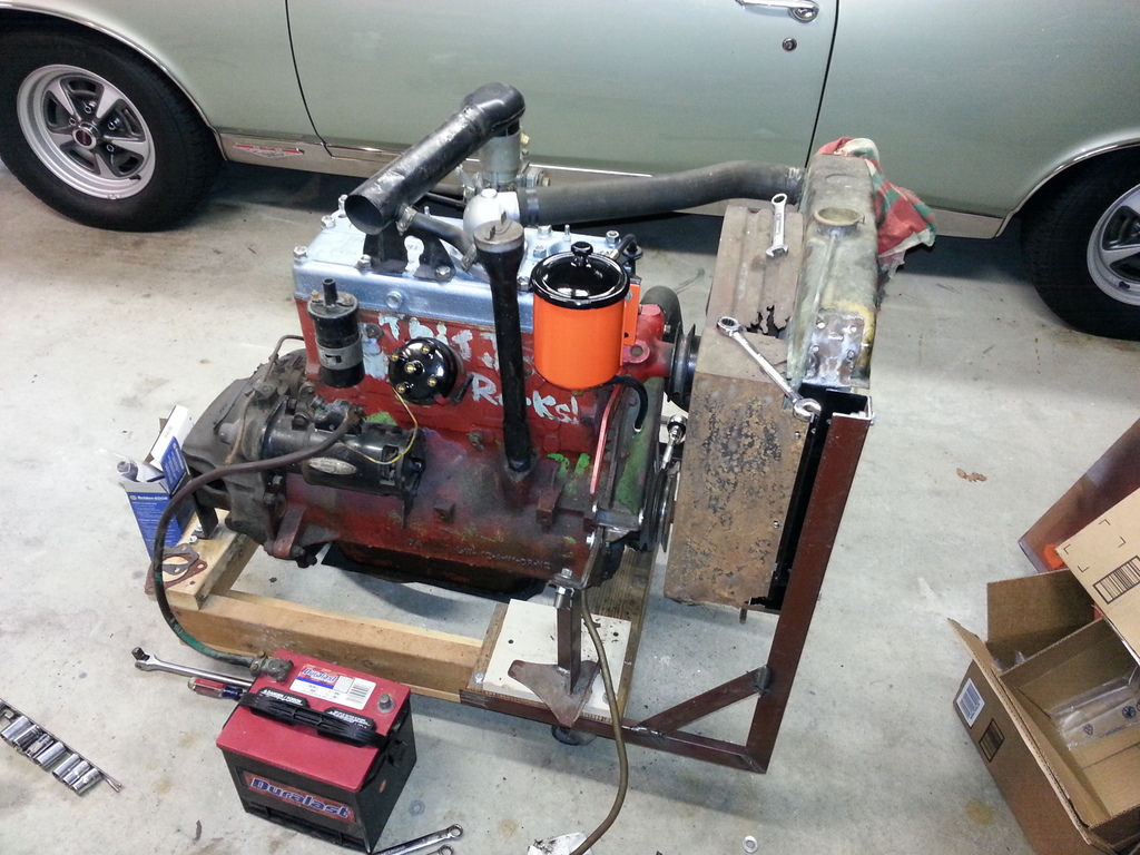
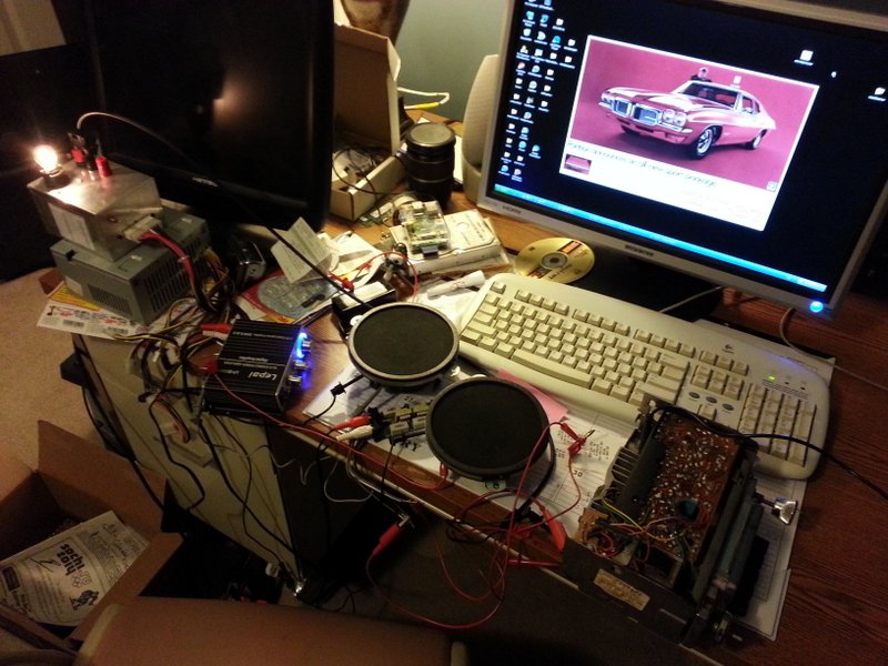
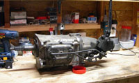
L134 Flathead Willys Engine
A
crude engine stand was my first mission. A cart was
fashioned with some lumber and casters. Old scrap steel was employed to
adapt the motor mounts and bellhousing to the cart. More scrap steel
was used to position the CJ radiator and shroud in front of the engine
to take advantage of the cooling fan. A small panel was made to hold
water and oil gauges,
as well as switches for the ignition and charging system (not shown
yet.) Note how previous owner did some custom stenciling on the side of
the block. Also note the head is not the same (keep reading below to
find out why).
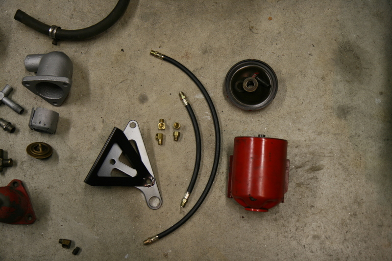
Bypass Oil Filter System
With the "stand"
ready,
the engine systems were next: The old
Jeep flathead engines (like many engines in those days) used externally
mounted oil filters, and I was missing many parts. I sourced the
external oil lines from 4wd.com, but got the
hard-to-find flare fittings at a local hydraulic supply company for a
few dollars. (It
pays to search around...there can be huge variations in costs across
suppliers, both local and online.
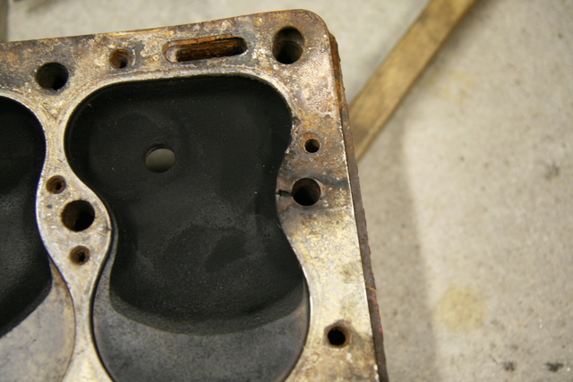
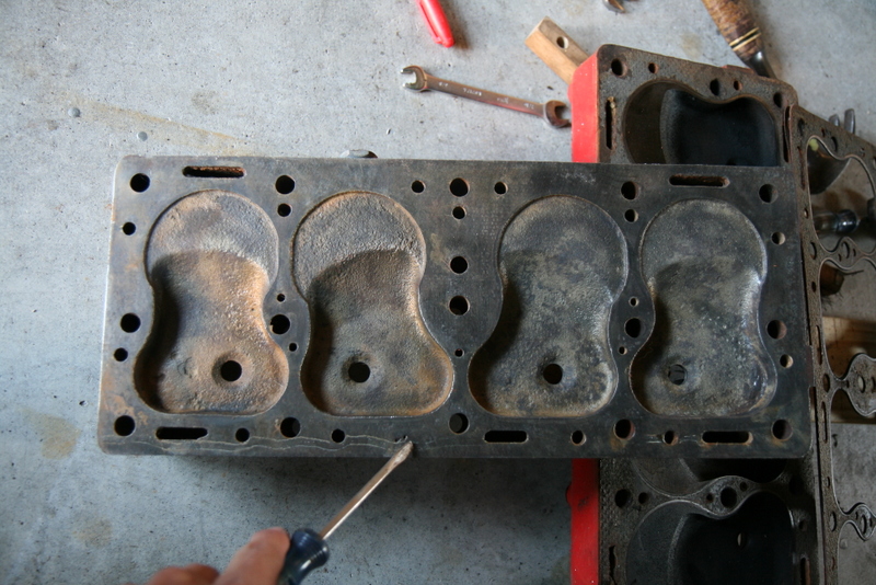
The installation
of a new
oil
filter mount disturbed a few of the head studs/nuts, necessatating a
re-torquing. Unfortunately one of the head studs broke while
approaching the torque value. So off came the head in order to drill
out the offending stud. While certainly a bummer, it did allow an
inspection of the pistons, cylinder walls and valves. The good news is
that it's in pretty decent shape and in fact still has standard bore
pistons.
It seems that a
crack in
the head gasket allowed gases to erode the stud which weakened it. I
managed to drill out and remove the stud without damaging the original
threads in the block. I sourced some Dorman head studs p/n 675-013 from
Amazon (sometimes you can get Dorman stuff on Amazon for extremely good
prices...woot) and switched to my blasted, cleaned, and crack free
"INDUSTRIAL" head
from the seized engine that came in the Jeep. (The head I removed from
the replacement engine was
riddled with cracks). I also inspected the tappets, and removed the
intake exhaust manifold which in turn required me to source new
manifold studs. I got those, shockingly enough, on a twirly rack at a
Pepboys.
Charging System
The original CJ Willys charging system was a 6 volt generator
with an external regulator. The components on the Jeep have long been
dormant and likely corroded beyond usefulness so I decided to "upgrade"
to a modern (well, 80's vintage) Delco 12si 3 wire alternator.
The
Delco alternator has internally regulated 12V output, it's cheap, super
reliable, and easy to use. The 12si is probably the ultimate unit to
look for (better internal cooling according to my research), but the
10si's are fine as well. The P/N I sourced is for a 1980 Camaro
application.
A
minor glitch when using a modern alternator is the
relatively narrow pulley that does not work well with
the
very wide "V" belt the L134 crank and waterpump use. There are
suppliers that sell wide "tractor" type pulleys, or you can
chuck the narrow pulley in a lathe and machine the "V" groove
wider.
Adapting a modern
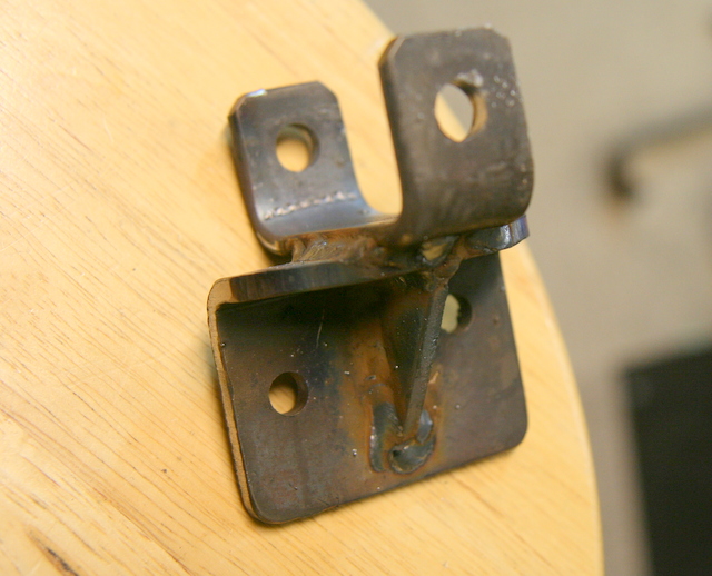
alternator to the little flathead requires a custom
bracket which can be had from some Jeep specialists online, but it's
easy to fabricate your own. My little box of scrap metal yielded enough
bits and pieces to weld one up. It's fairly thick steel so I used a
propane torch to preheat the metal for better penetration.
Last
thing to do was to replace the cap, rotor and ignition wires. I figured
the rest should be okay since it was advertised as running when I
bought it. At the first start attempt, cranking speed was normal, but
there was no sign of a pop. A test for spark (with a removed spark
plug) was positive, but there was no ignition when installed. I put in
a new coil, and still nothing. I replaced the points, and bingo!
Instant ignition.
A few leaks were attended to, and a few minutes of
run time indicated a dirty carburetor. The solex carb has a bunch of
plugs and caps that can be removed to access internal passages. I
removed all of them and blasted everything I could with carb spray
cleaner. A dramatic improvement to idle quality was observed and after
a little warmup, it revved nicely too. There is a bit of blue smoke I
think from leaky valve guides, but this little flathead is a decent
runner.
I made up a low quality phone video of the running engine:
Coming soon: The Willys Jeep CJ3A drivetrain
test
stand!
Delco AM Radio Project
April 4, 2014
The
GTO on these pages was born with a classic Delco pushbutton AM radio.
Luckily enough, the radio was in a box of stuff that came with the car
when I took ownership. I wasn't interested in an AM radio back then, so
I just stored it away. So, decades later, I'm
interested in getting the dash back to it's vintage look. But, since an
AM radio is pretty low tech, I did a few things with very inexpensive
components
to get an "aux" input as well as stereo output capability.
AM Radio "Refurb"
First
thing to do was to test the radio I have. My original 10 ohm speaker
was toast so I put two 4 ohm speakers together in series and
hooked it up. After a few wisps of smoke (probably from 30 year old
crust on the volume pot) it seemed to work.
Even
with a positive sign of life, I decided it would still be prudent
to replace the seven electrolytic capacitors in the unit.
Three of
these capacitors are on the underside of the top circuit board
which entails desoldering the tuner housing and removing a few 1/4"
nuts.
The board can be folded up onto it's side to gain access to the caps.
With the board tipped out, replacing those three caps was easy. (mind
the polarity!....the board actually has little "+" signs on the traces)
The three capacitors are easily identified with their silver case and
"DELCO" stamp. They have date codes too, and mine were from early '67.
Interestingly, a friend of mine tested the three original Delco
capacitors after
removal and they all tested very good. Oh well. The board was laid back
down and soldered and screwed back into place.
The
remaining 4 capacitors reside in a huge aluminum can at the back
corner of the radio. This large can is filled with coiled foil within a
gooey oil. I simply bypassed this by constructing a small board to
which I mounted 4 replacement "modern" capacitors of similar values.
Modern capacitors are much smaller so there was plenty of room to fit a
small board. (See picture above) The leads to the original "can" (which
can be partially seen behind the new light blue caps) were
desoldered, lengthened as necessary and connected to the new caps.
(mind the polarity!) The radio was then tested again, and it worked
fine,
but my friend still did the full adjustment suite on the thing; it
involves connecting all sorts of equipment...turning trimmers....my
eyes glazed over...so I just watched. The output transistor voltage was
fluctuating a bit, and we could not find the cause, so we just let that
be.
Besides
replacing the capacitors, I removed the front faceplate and cleaned all
the dust and gunk from the pushbuttons. I also removed the faceplate
and repainted the orange dial pin, and finally repainted the "PONTIAC"
script on the faceplate.
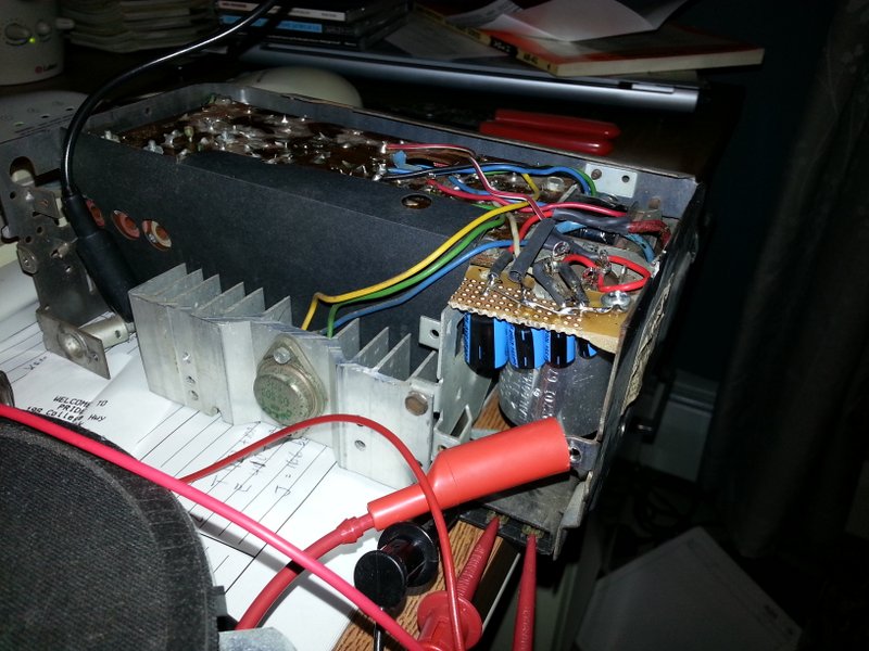
Additional Equipment
So,
now the radio looks good and works fine.
If I stopped here, I'd have to buy a new 50 dollar 10 ohm speaker and
I'd have a working AM radio. But, I would like to have some modern
options like FM, and even an "aux" input. There are companies that I
could send my radio to for a "conversion" which entails loading it with
a tiny AM/FM IC chip. Another option is to just get a new "retro"
radio. But all these options cost hundreds.
To just get FM capability, I considered an
old
fashioned "FM Converter" which would be kinda cool, and definitely old
school. But ebay searching indicates that these are hot right now, and
buying a crusty used converter for 50 bucks or a never used unit for
$100 bucks was not appealing.
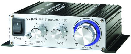
Investigating possibilities further led me to
these mini stereo amplifiers. There is a family
of mini stereo
amplifiers that can take a "line level" input, an mp3 device input, and
put out extremely good quality stereo sound. I chose the Lepai
2020+. It uses a Tripath 2020 IC
chip which caused quite a stir in the audiophile community when it came
out. This amplifier is something like 20 bucks, comes in a
pretty
small case, is very efficient, and runs cool.
So
to make this thing work, I needed to convert the mono speaker level
ouptut of the DELCO AM radio to a line level output suitable for audio
amplifiers. To do this, I used a simple, passive line out converter. I
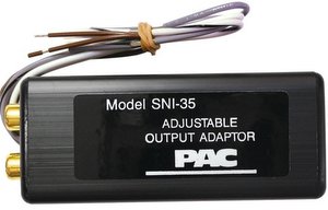
chose the PAC
SNI35 which features a voltage divider/transformer network to convert
the speaker output of any radio to "line" levels.
The
converter is meant to receive and "adapt" stereo speaker inputs, but
you can input a mono source: I just
connected the single speaker output of the DELCO to both "+" inputs of
the line out converter. The "-" inputs of the PAC were all tied
together and connected to chassis ground. The converter also
has two ground
wires that can be connected optionally (the brown leads) and they
indeed reduced noise when also connected to chassis ground.
The
output of the line out converter has RCA jacks. So a simple RCA cable
was run to the RCA jack input of
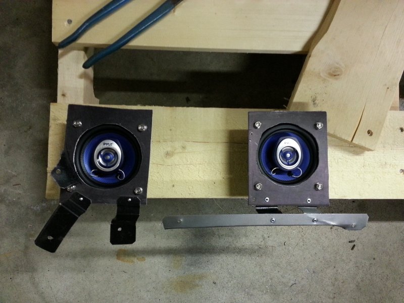
the Lepai amplifier. Finally, I connected a pair of 4" PYLE coax
speakers to the
Lepai amplifier. I chose the 4" speakers because I thought might be
able to fit the pair side by side into the original speaker location up
under
the dash. But, the magnets are just too big and they wouldn't fit. So,
I
fashioned some crazy mounts to
fit them in the void areas down low behind the dash. I made square
plates out of 1/8" aluminum to screw the speakers to, then
bent up some
sheet metal tabs to adapt the speaker mounts to existing holes near the
intended
locations.
The speakers point down but sound
pretty darn good. The
right speaker fit on the right side of the glove box which can be seen
in the picture below. It is held in
with three brackets and that was enough to make it sturdy. I used two
existing holes for mounting, but I did have to drill one hole on the
underside of the metal lip of the dash.
The
other speaker fit on the left side of the glove box, but this one did
require making a long strut that I tied into
a defroster duct screw.
In Summation
So,
instead of spending 50 bucks on one speaker just to get AM radio, I
spent about the same amount for a line out converter ($11), a stereo
amplifier with "line" and "aux" inputs ($20), and a pair of 4 inch coax
speakers ($18). The beauty of this set up is I can:
1) play the AM radio through the amplifier which powers the
two speakers with high quality sound,
2)
plug in an iPod directly into "aux in" input of the amplifier which
then plays my music and podcasts, or,
3) play FM radio through the same
auxiliary input.
The FM option is kind of cheating since it still
has to come from an external source, but some ipods have FM
capability and it's simple.
Downsides?
Well, it took quite a bit of time to fix up the original radio, then
time to fabricate up some speaker mounts, and then time to just wire
and solder all the components together. And, critically
speaking, there is now a funky box mounted under my
dash.
However, subjectively speaking, the little box looks
kind of cool; it basically
looks like a modern version of an FM converter. And as for the time it
took to cook up this rig, my labor is cheap, and it's kinda fun to do
these projects.
So,
this definitely is not an option for show cars. But for driver cars,
it's a funky hybrid kind of set-up; it's sanitary looking, the original
radio still fills the dash, you get stereo sound, and it's CHEAP!
I
want to give a big thanks to GT182 (from Performance Years forums) for
giving me a couple AM radios to use for parts. They also came in handy
for testing to compare voltages and signals.
Muncie rebuild
Muncie Rebuild
The most popular page on this site is up and running. That's
the GM muncie 4 speed
rebuild. This trans was purchased to swap into an automatic
GTO.
The GTO trunk body work page highlights some extensive
wheelwell repair, trunk pan and braces installation.
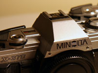
Minolta
SLR stereo rig
Stereo Camera Rig
Also added is a
cool project for a
Stereo
camera setup
using older Minolta SLRs. This technique makes stereo pairs with slide
film. A simple viewer of the pairs shows awesome 3D pictures.
DIY Microphone Preamplifier
July 2009
Click
the pic to check out the latest with my mic preamp. The preamp has been
fired up. It works, but I still want to do more testing with different
opamps. I'm researching ways to attach mp3 samples soon too.
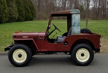
There exists a nice set of webpages for CJ3A's. It's got a forum too that caters to both '3A's and CJ3B's. It's a great resource, and frequented by very knowledgible folks.
1967 GTO Original Owner
These two videos feature an original owner GTO. This car was featured in Hemmings Muscle Cars magazine a couple years ago. Part 2 has inside and outside shots of the owner driving the car. Very nicely done.
Blues Maker
"Mississippi" Fred McDowell. One of the great Bluesman. This is a documentary made in 1969.
Pinstripes
Pinstriping the ol' fashioned way. Pretty nice.
MGB Racecar
I've always liked MG's. Watch this MGB lift it's inside tire a few inches off the tarmac when going "'round the bend". Awesome.
Pepsi Throwback
Pepsi has put out a "limited edition Throwback" version of
Pepsi with REAL sugar, instead of high fructose corn syrup which has been used since the 80's. Holy cow
there IS a difference; it's WAY better. Find some quick!


 After
getting it home, a quick survey revealed it needed a replacement engine
and in 2009 I found one, but I stuffed it into a corner and the Jeep
continued to languish.
After
getting it home, a quick survey revealed it needed a replacement engine
and in 2009 I found one, but I stuffed it into a corner and the Jeep
continued to languish.